I started the Bubble Dancer with the Fin. Unfortunately, I was mostly done with the initial assembly before I got the idea to make a build log and take pictures...
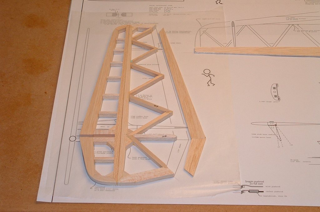
So here is the first shot of this project Fin already underway.
One thing to note, the Bubble Dancer design seeks to minimize weight at the extremities. This is certainly the case with the fin and rudder, where the further out you go, the thinner the stock is that you use.
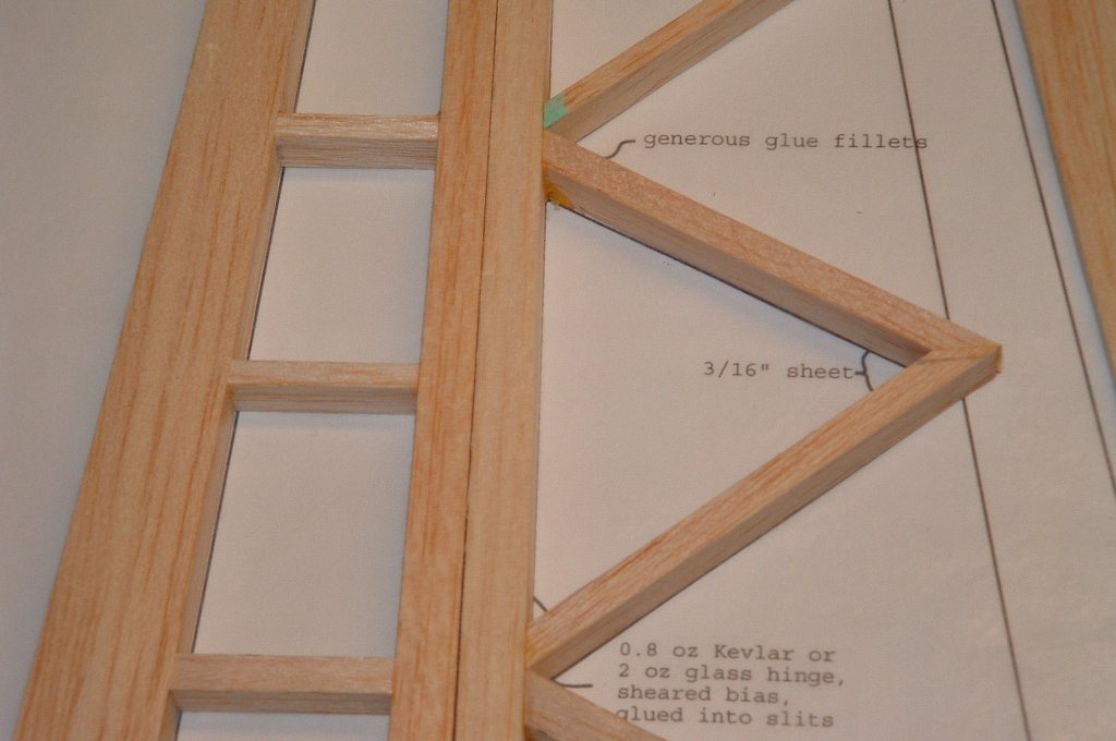
The Bubble Dancer requires precisely mitered angles.
Go get yourself some sort of Miter Saw and Miter Sander as without them you won't have success here.
Even so, careful trial fitting and sanding is required to get it just right. -- I had to toss more than one failed piece.
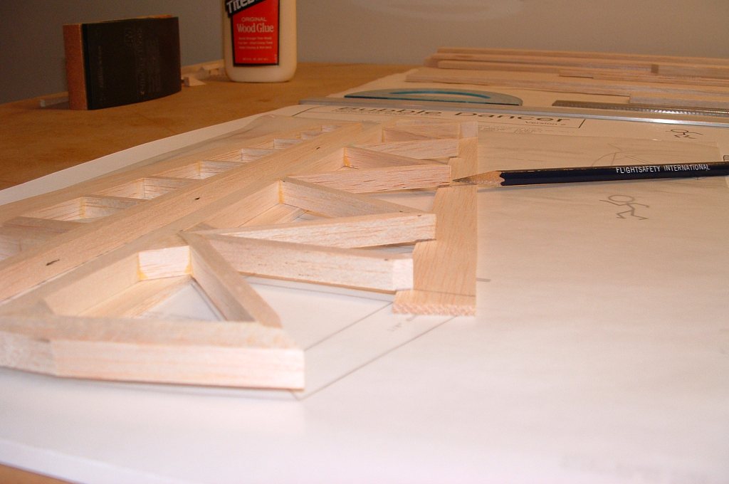
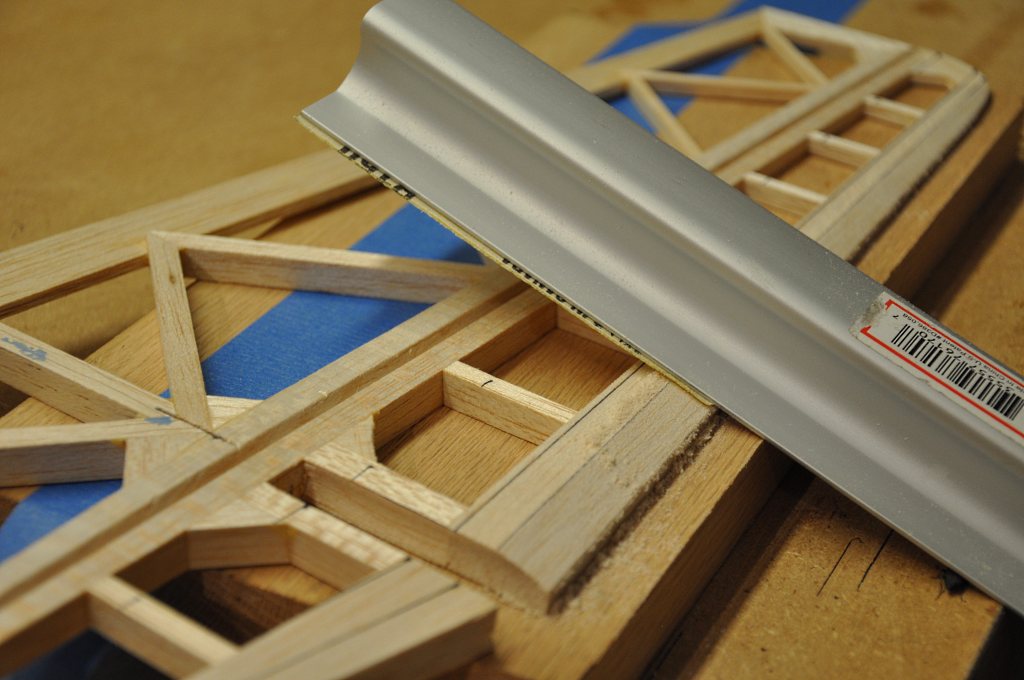
I chose to build from the front to the back which meant I had to notch the trailing edge after the diagonals were set.
I placed a shim made of the trailing edge stock under the rudder to elevate it enough to lay the trailing edge under the diagonals and then marked the notch locations with a pencil.
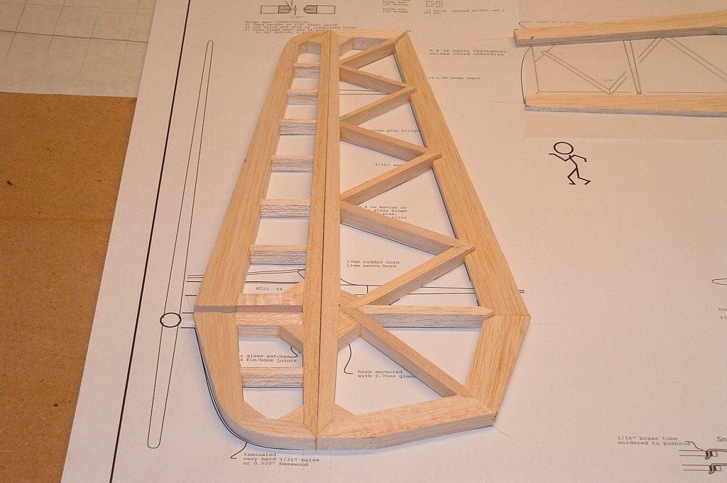
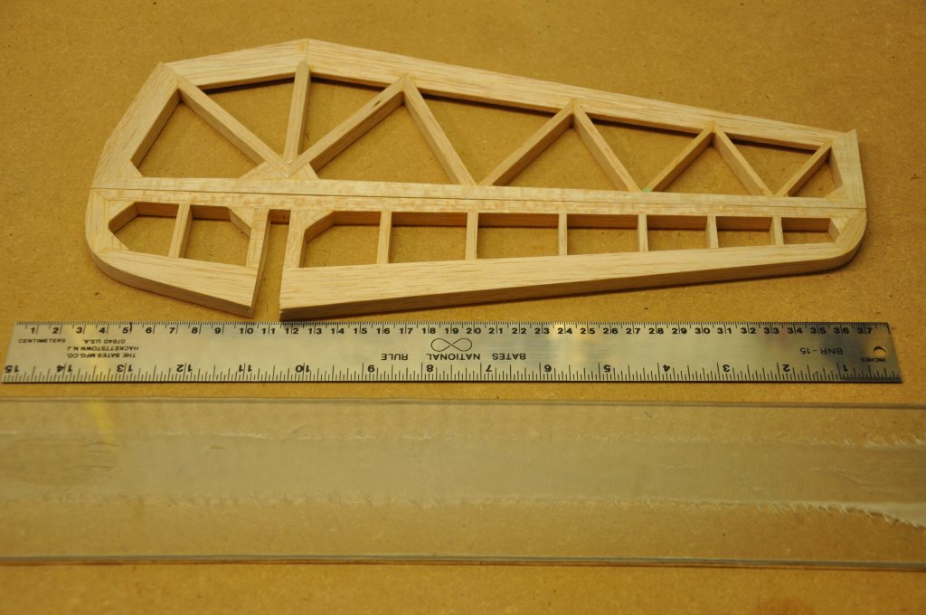
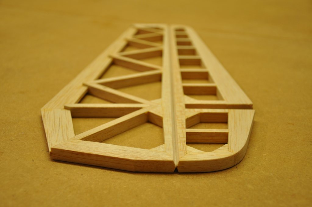
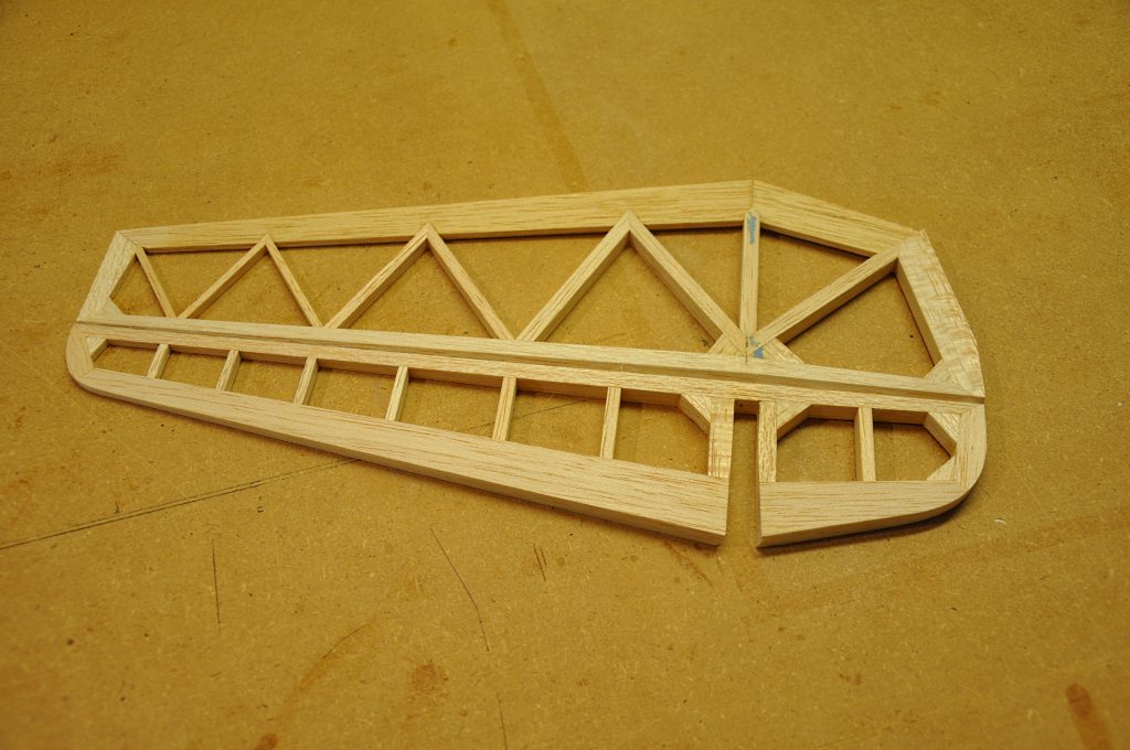
The main fin and rudder structure is complete.
Shaping the airfoil is still needed. This will be accomplished with long sanding blocks and shims.
It was suggested to me to install the hinge next, taking advantage of the square, flat stock to make cutting the hinge slot easier. The other advantage being that the hinge would hold both halves together making it easier to shape the airfoil.
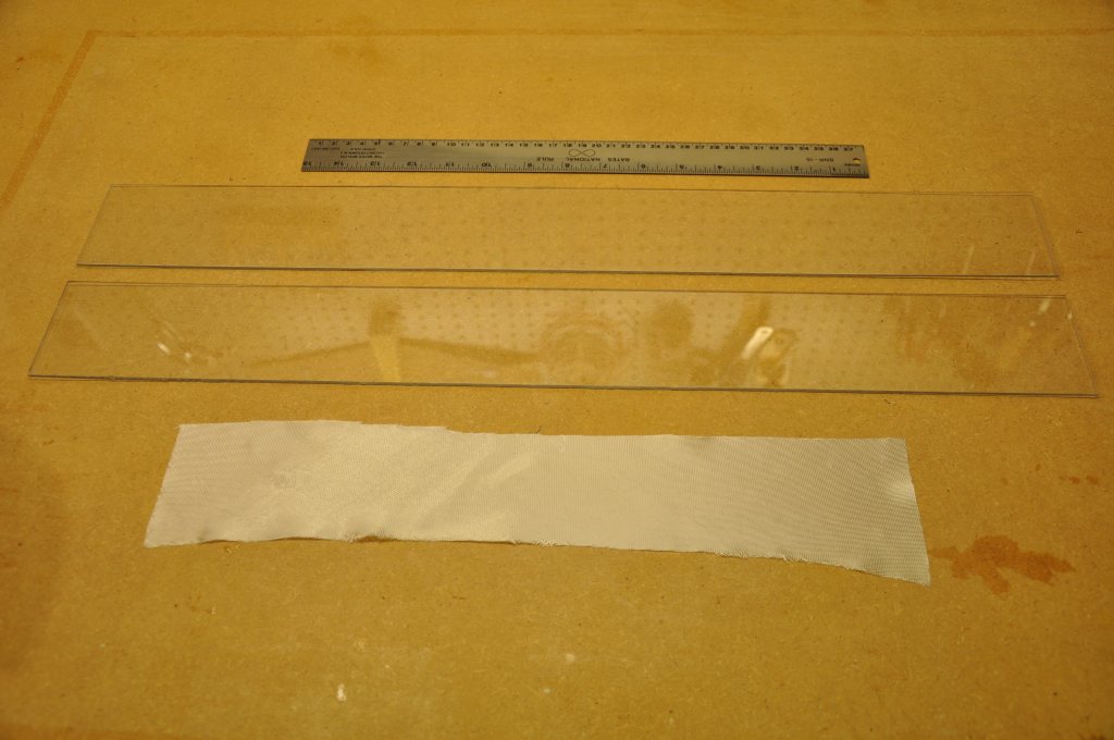
To make the hinge I cut a strip of 2oz fiberglass (Kevlar is another option.) on a 45 degree bias.
I prepared two plexiglass pieces with which I could sandwich the fiberglass.
I painted some epoxy on the bottom plexiglass and stretched the fiberglass as long as it could go. Then I set the glass in the epoxy.
When it was wetted out, I dabbed up as much epoxy as I could, covered the glass with the top plexiglass and allowed it to cure.
Once the epoxy cured, I removed the hinge from the plexiglass.
I then cut the hinge from the strip.
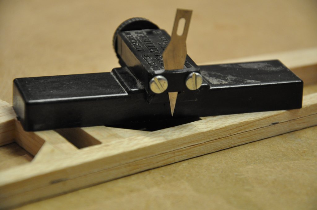
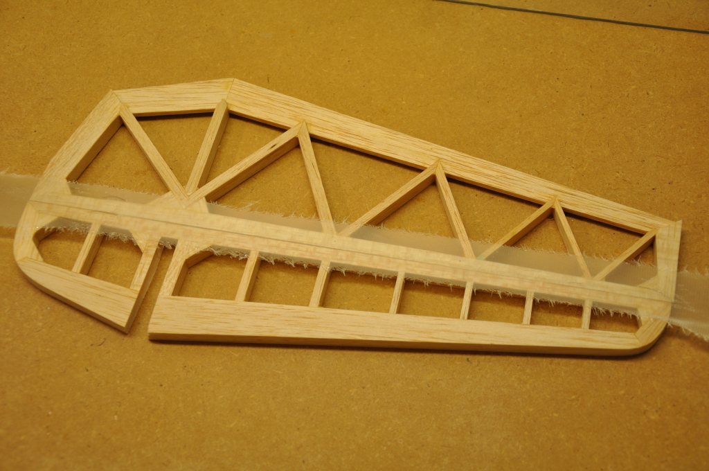
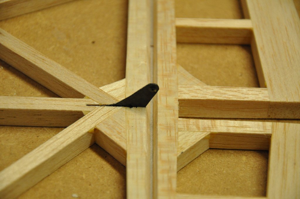
Next I used my balsa stripper to cut the hinge slots in the fin and rudder.
I set the blade at the depth needed and set the tool width to fall exactly in the middle of the balsa. - I double-checked that I was precisely at the mid-point by testing the cut from both the left and right sides.
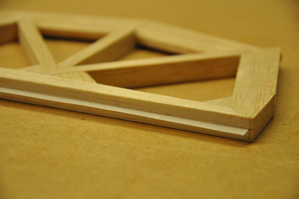
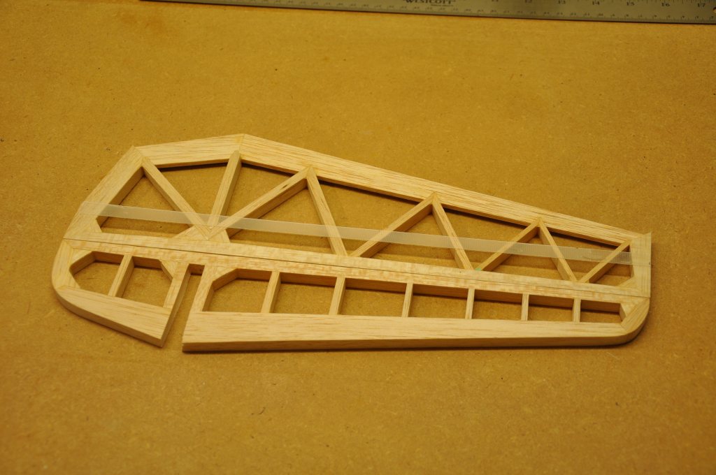
Here you can see the hinge set into the rudder.
Finally the hinge-line bevel was sanded into both sides of the assembly.
The plans call for a 25 degree bevel.
I glued the hinge in place and made sure that it flexed properly.
Next it was time to sand the fin-to-boom joint.
I carefully wrapped some sandpaper around a dowel that was smaller in diameter than the narrowest end of the boom. By successively wrapping the sandpaper up this dowel I achieved a tapered sanding dowel.
I then carefully began twisting the joint over the dowel until I could force it deeper and deeper down the fin.
Eventually I got to the end and I had a rounded joint the fit on the tail boom.
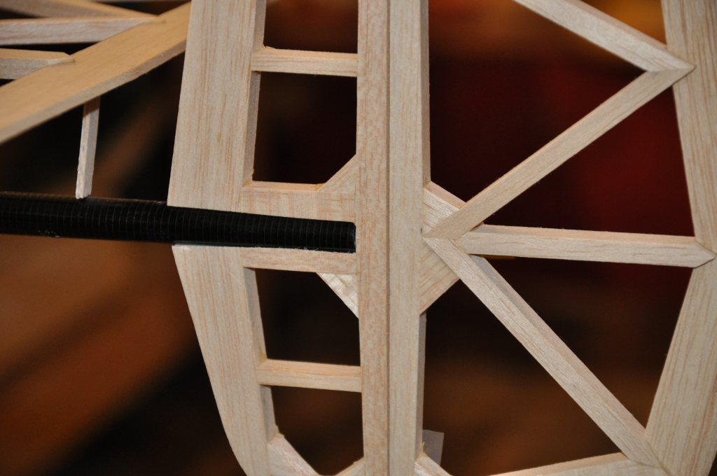
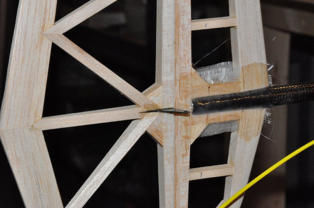
Next, I carefully notched a slot for the carbon fiber control horn - (purchase from Bud Elder).
The horn will be epoxied in place later, and will have some glass reinforcement, as called for in the plans.
Note: care was taken to ensure that the center of the horn lines up with the center of the hinge line.
To shape the fin, I followed the documentation available on the CRRC website.
Here is my interpretation of that documentation:
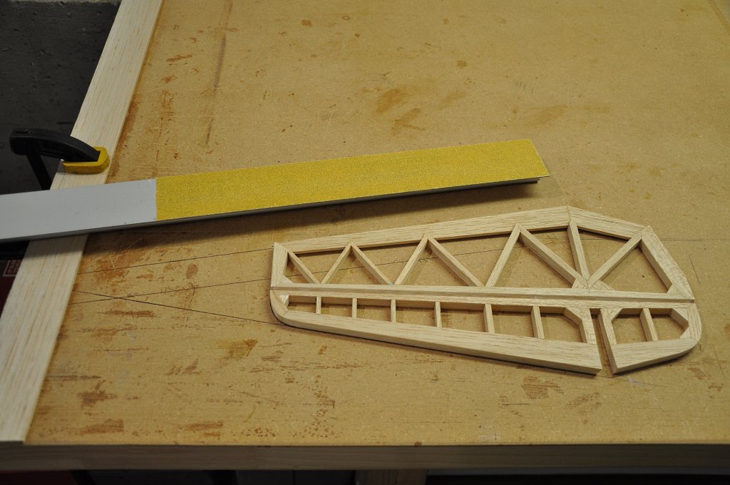
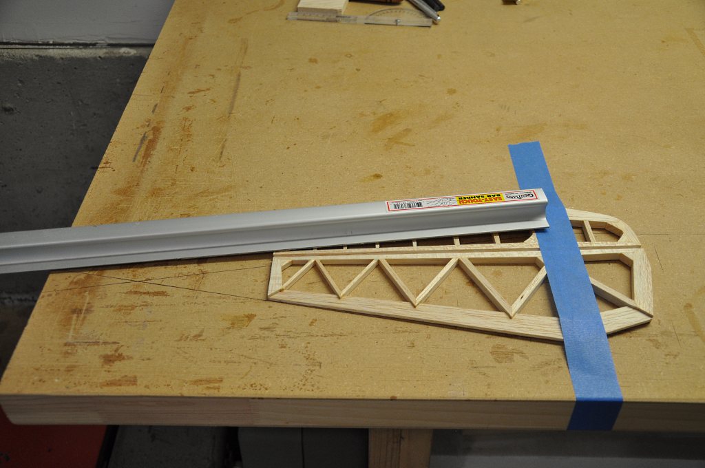
I drew out extended lines from each edge of the fin to converge at the edge of my workbench.
I then prepared my long sanding bar with 80-grit sandpaper on one half of the bar.
I taped across the fin at the location where the tapering ends to protect the wood from inadvertent sanding.
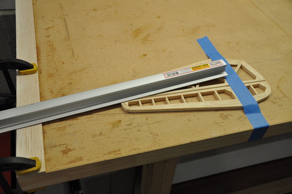
Next, I placed a half-thickness balsa shim at the bench edge on which the smooth portion of the sanding bar would rest.
Then I began sanding across the fin until the end of the bar began lightly scratching on the blue tape.
Once the first side was done, I removed the shim, flipped the fin over and sanded the other side in the same fashion.
In this way an even taper is achieved on both sides.
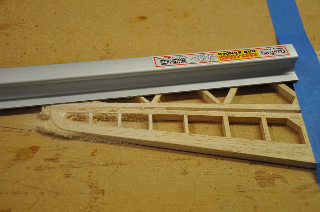
I then repeated the process to taper the bottom portion of the fin.
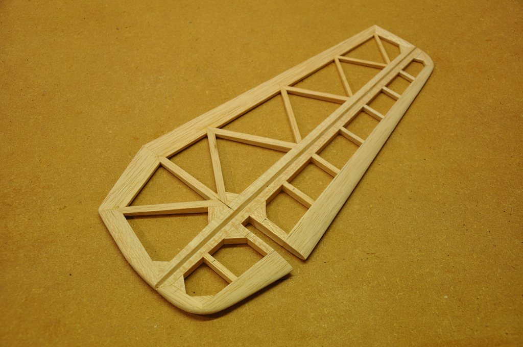
Here is the fin after the tapering has been accomplished in the span-wise direction.
Next I needed to sand in the airfoil shape.
I marked off 3 lines on both sides of the fin: at 5%, 10% and 25% chord line.
Then using the slope values given on the plans, I set the fin on my oak board and set the board back from the edge to achieve the correct slope.
Using a shorter sanding bar with sandpaper on half of the bar, I carefully sanded the slope up to the first line. I then reset the slope and sanded to the second line.
After that, I turned the fin around and sanded from the 25% line to the trailing edge to finish the rough airfoil shape.
Final shaping of the fin's airfoil was achieved with lighter-grit paper to round off the rough edges.
Here is the fin after shaping.
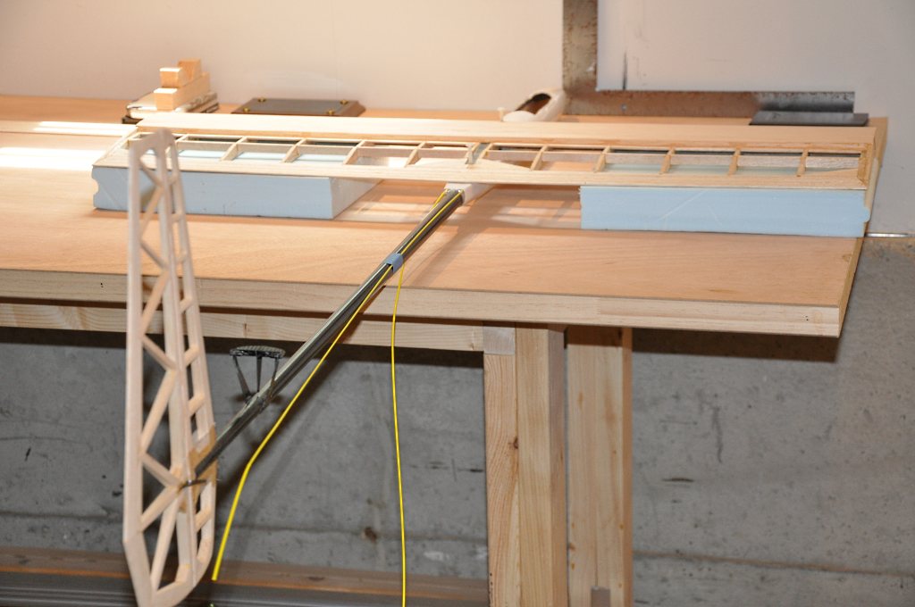
I set up a large metal square at the pod centerline and then attached the center panel to hold the fuselage in alignment.
I mixed up some thickened epoxy and glued the fin to the tail boom.
I then lightly painted regular slow cure epoxy on the fin and placed a fiberglass doubler over the fin to tail boom joint.
Here is a close-up shot of the fin attachment with the fiberglass doubler gluing.
After the glue had hardened enough, I cut away the excess glass with my knife. I lightly sanded over the glass to smooth everything out and prepare it for covering.