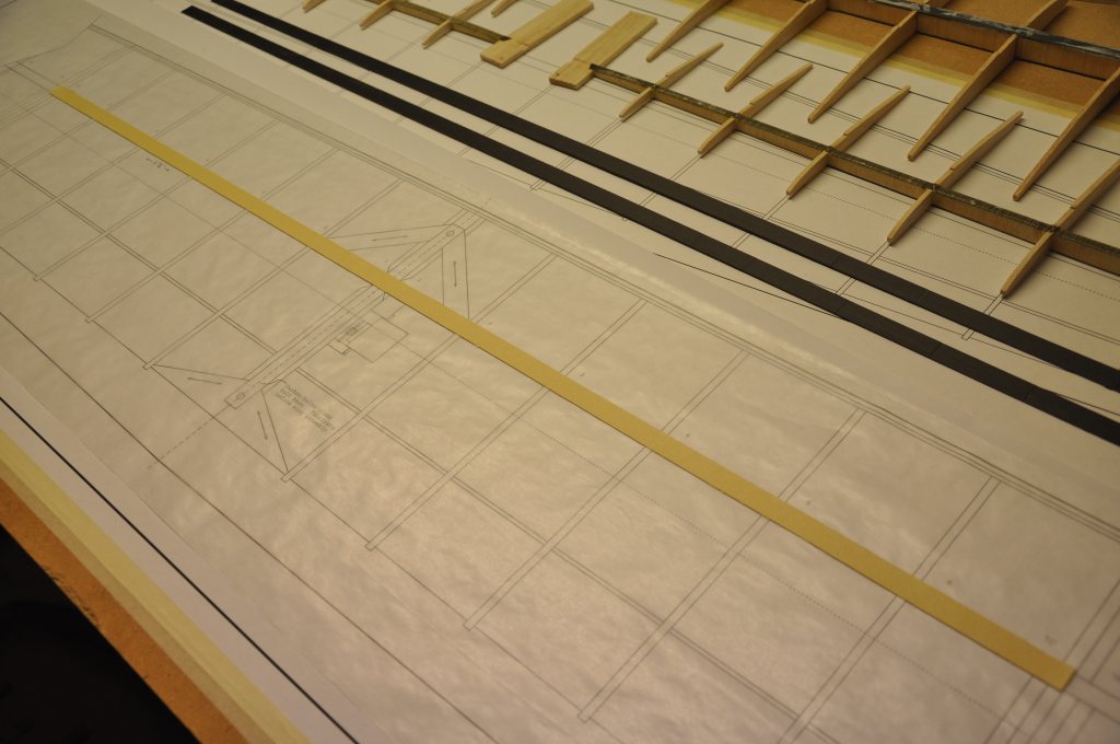
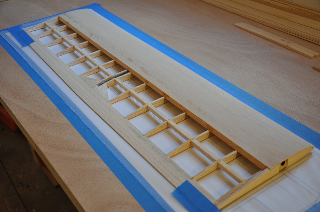
As with the all the other wing panels, I cut the plan to size and taped it to the workbench. I also covered the plans with clear plastic.
Next I laid in place another one of my homemade masking tape shims, which will provide the proper offset for the bottom spar cap so that it will fit snugly against the ribs when they are set in place.
After the tape shim was down, I placed the bottom carbon spar cap in place on top of the shim.
In this picture you can see the top spar cap is ready for placement once the webs and ribs are in place.
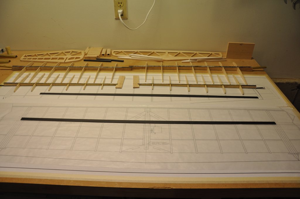
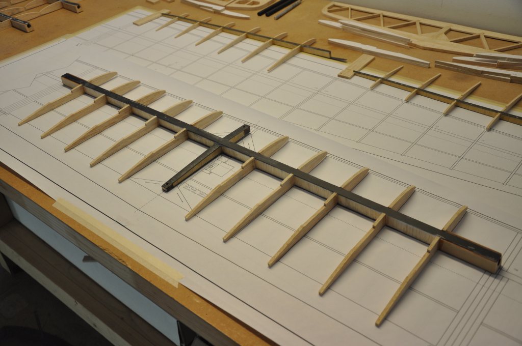
Next I test fit all my ribs and webs to ensure that I was ready to glue up the spar assembly.
Once satisfied with the fit, I mixed up the thickened epoxy and began placing the ribs and webs.
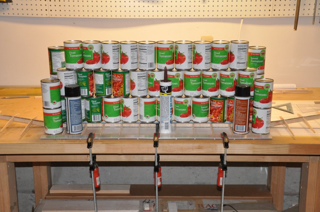
Once all the ribs, webs and carbon spar caps were buttered up and set in place, I raided the pantry again for cans to weigh down the spar assembly.
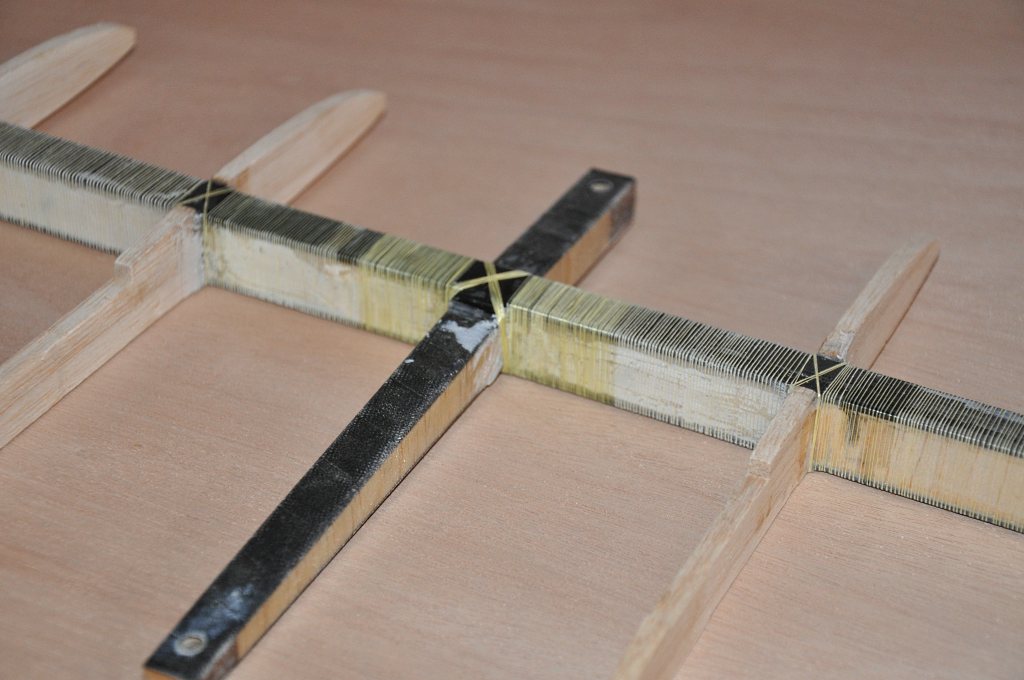
While setting up the center spar, I also attached the mid panels to the center spar joiner blocks via the brass tube that I had left uncut for that specific purpose.
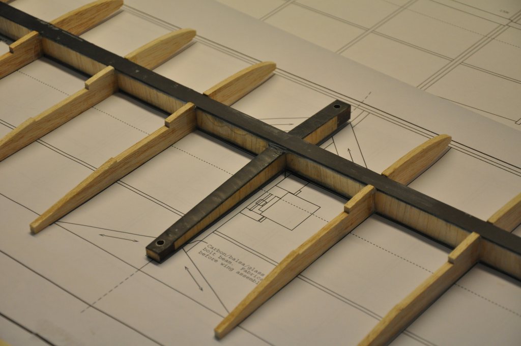
Since the epoxy was slow cure, it allowed me plenty of time to get the center and mid panel wing joiners in perfect alignment. This was not a step I could afford to get wrong so I took my time and ensured that I achieved the correct fit.
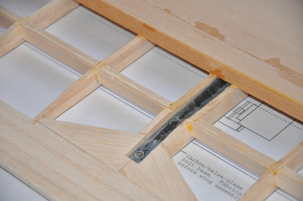
Here is a close-up of the alignment of the center and mid panel wing joiner on the left side of the wing.
Once the glue cured, I carefully pulled the brass tube from one side and then cut it in half. Then I re-inserted each tube into position in the joiner blocks.
The alternate joiner tube is of course made from Kevlar for weight savings, and you can read about how to make those tubes on the CRRC Bubble Dancer website.
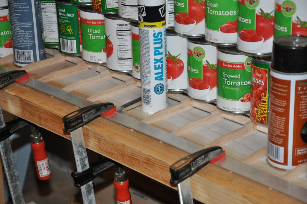
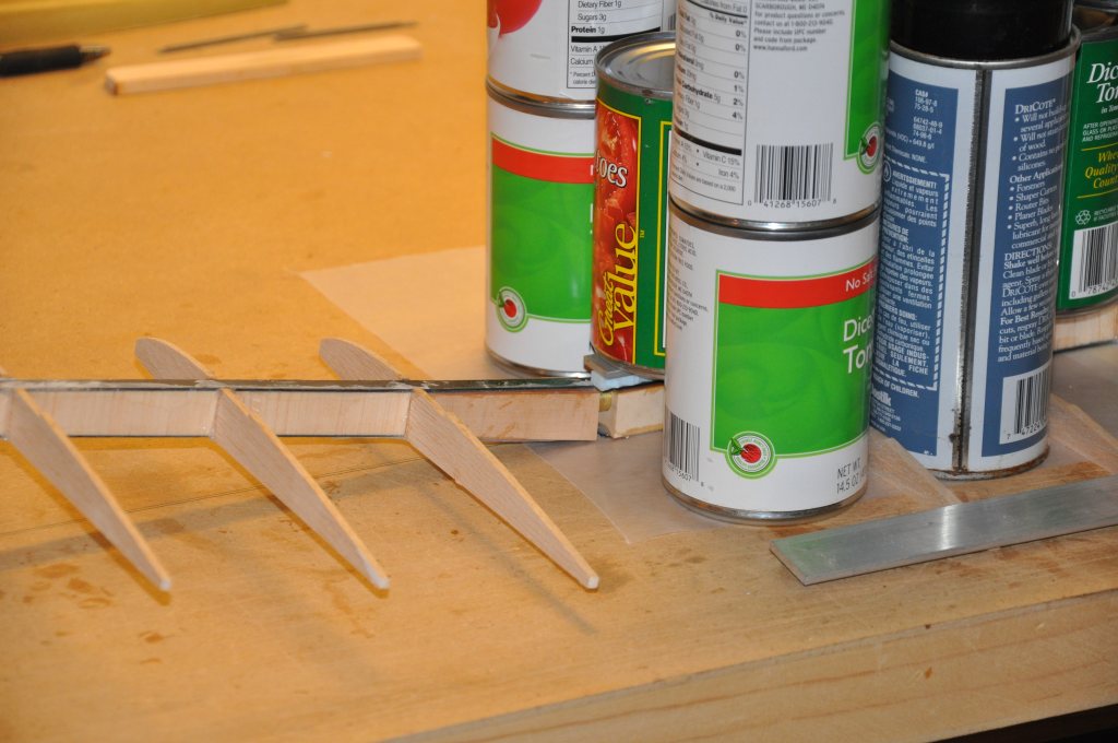
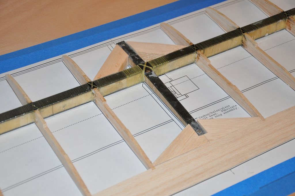
I included this shot of the center spar glue-up just to draw attention to the bar and claps that I used at the trailing edge of the ribs.
The airfoil is flat aft of the spar, but with all the cans stacked on the spar, I was having a hard time keeping the assembly from rotating to the leading edge. By clamping the back down in this fashion, I was able to keep the panel flat and true.
I allowed the assembly to cure overnight and the next morning re-stocked my wife's pantry. -- Extreme care was taken to return all cans to their proper shelves in order of expiration date... :-)
As much epoxy splooge as possible was cleaned up during the setup, but some had to be removed after the cure. I cleaned what I could with a blade and then finished with sandpaper where needed.
Note: You will see that I made my joiner blocks slightly wider than the plans specified. I did this mainly because I used solid basswood and just wanted a bit more wood around the hole. My recommendation would be to follow the plans.
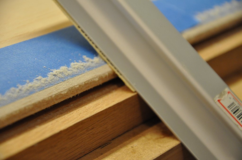
To prepare the spar for Kevlar wrapping I needed to round off all the sharp corners on the carbon spar caps.
You can see in this close-up just how sharp the carbon edges can be. I wet down my sanding block and carefully rounded off the edges. -- Be sure to wear a breathing mask for this step.
Once the spar was prepared, it was time again to wrap the spar with Kevlar.
As before, go for good tension on the line while wrapping and make steady, consistently spaced wraps.
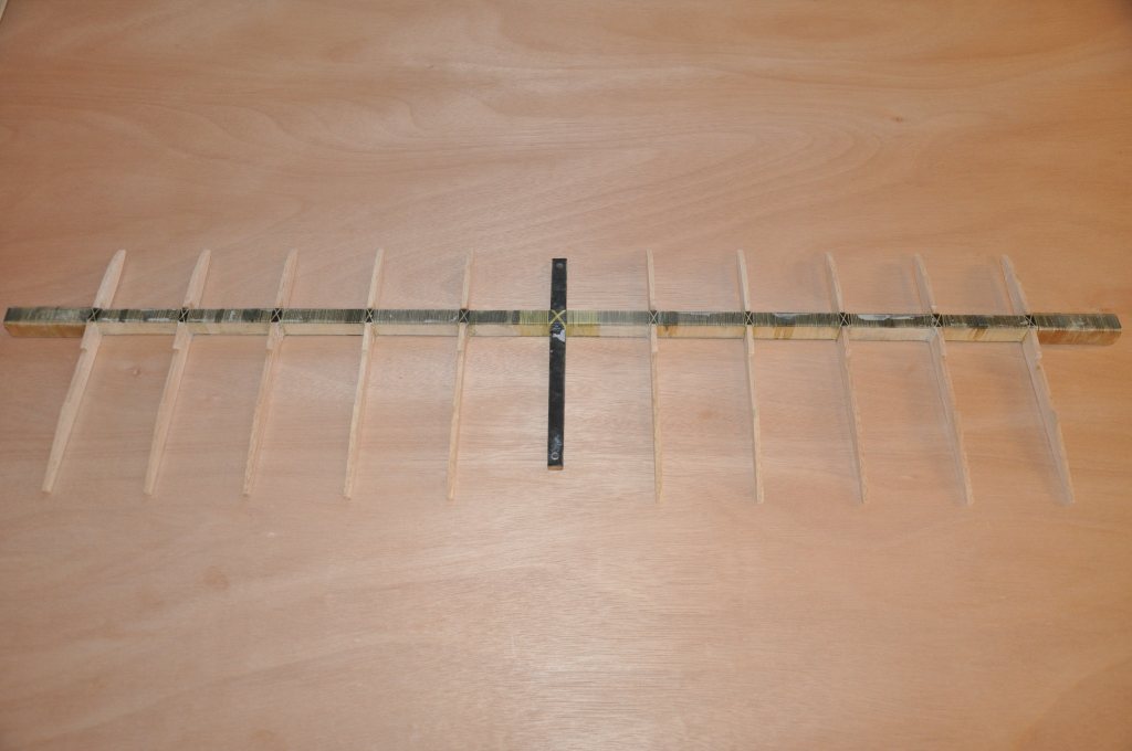
This shot was taken once the wrapping was finished.
A second wrap of Kevlar was applied over the first at the very center of the panel. We want to ensure that this joint between the bolt beam and spar is strong.
After the wrap was done, I brushed the Kevlar with epoxy to lock the thread in place.
The trailing edge received the same notching treatment as the trailing edges of the other panels - see the tip panel write-up for details.
I shaped and glued in place the thick balsa wedges that secure the bolt beam to the trailing edge.
Next I glued in the angle supports that connect the front of the beam to the spar.
These pieces were glued in with thickened epoxy to ensure a good joint.
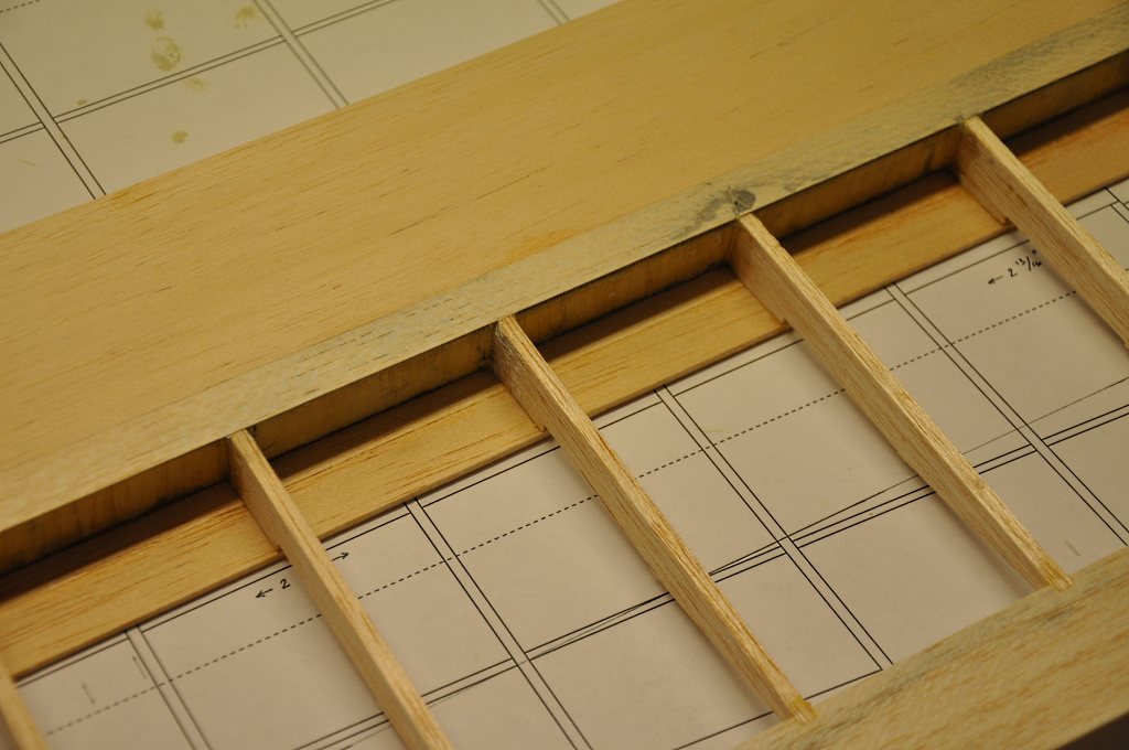
Just a close-up shot of the joint at the trailing edge in the center of the panel.
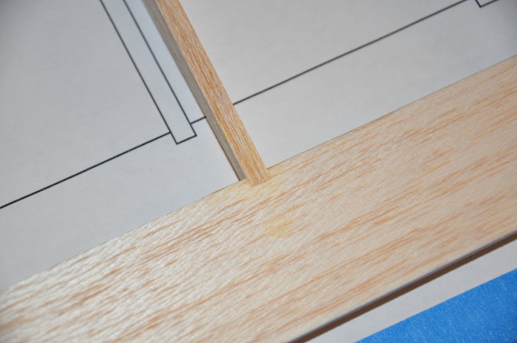
Another close-up shot at one of the other rib to trailing edge joints showing the notched joint.
Most of these joints needed no further attention, but I passed a sanding block over them to ensure that they were flush with no hard spots of glue.
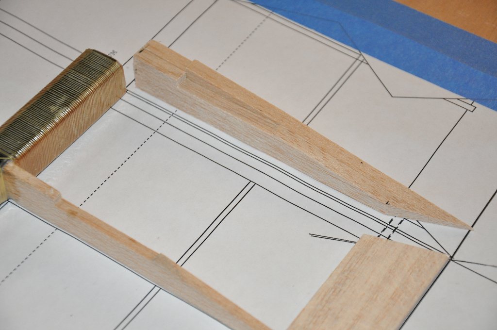
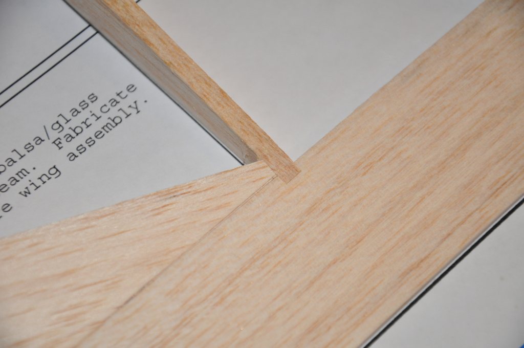
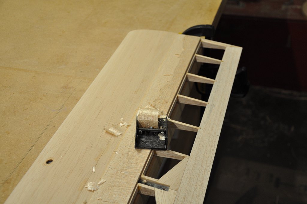
At each end of the center panel there are 2 ribs that are installed as a unit. The inboard rib has a notch for the spoiler, the outboard one does not.
These ribs do not run full length from leading to trailing edge. Instead they fit in front and behind the spar. I cut them to length and then carefully mitered the prescribed angle into the ribs and matched that angle on the trailing edge.
Once satisfied, I glued them to each other with wood glue and to the spar with thickened epoxy.
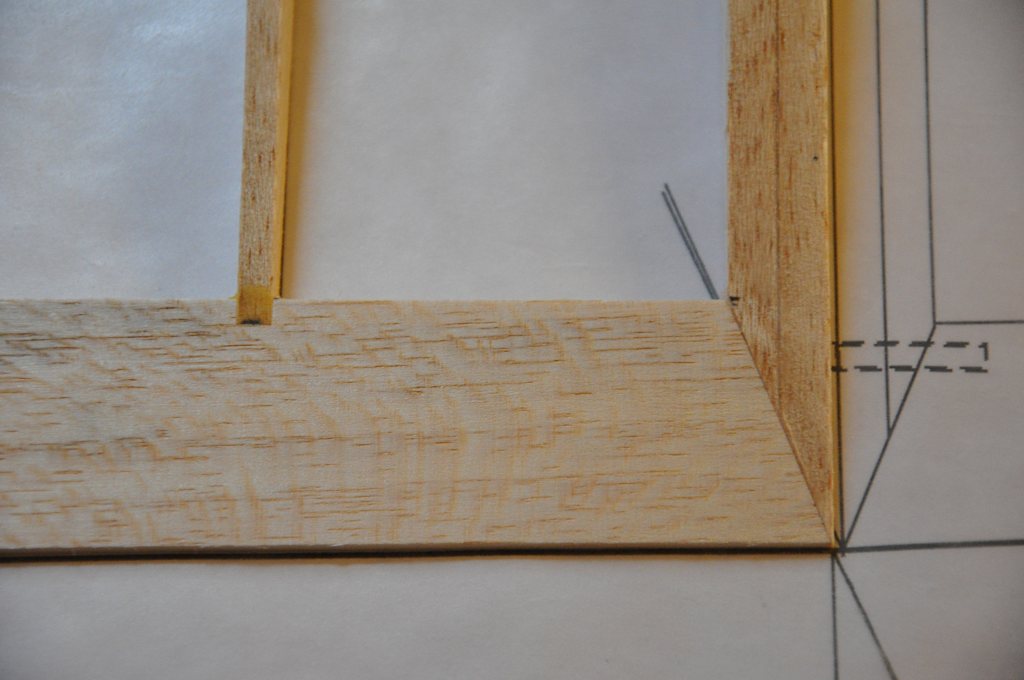
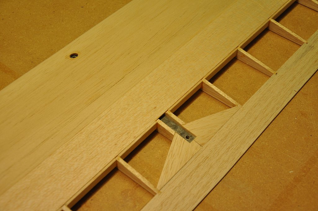
One of the finished joints.
As a cutting aid, I extended the line of the joint angle on the plans to help guide my saw. (I actually freehanded the cut.)
Next I glued in the inner leading-edge strip and the bottom and top sheeting.
Once the sheeting was in place I glued in the 1/32" balsa spar cap strips to cover over the Kevlar wrap.
The strip is simply there to even everything out so I carefully sanded the cap strip to the contour of the wing. You will note that in some places it got so thin that the carbon spar cap became visible again. That's ok, the main thing is to ensure that the airfoil contour is true.
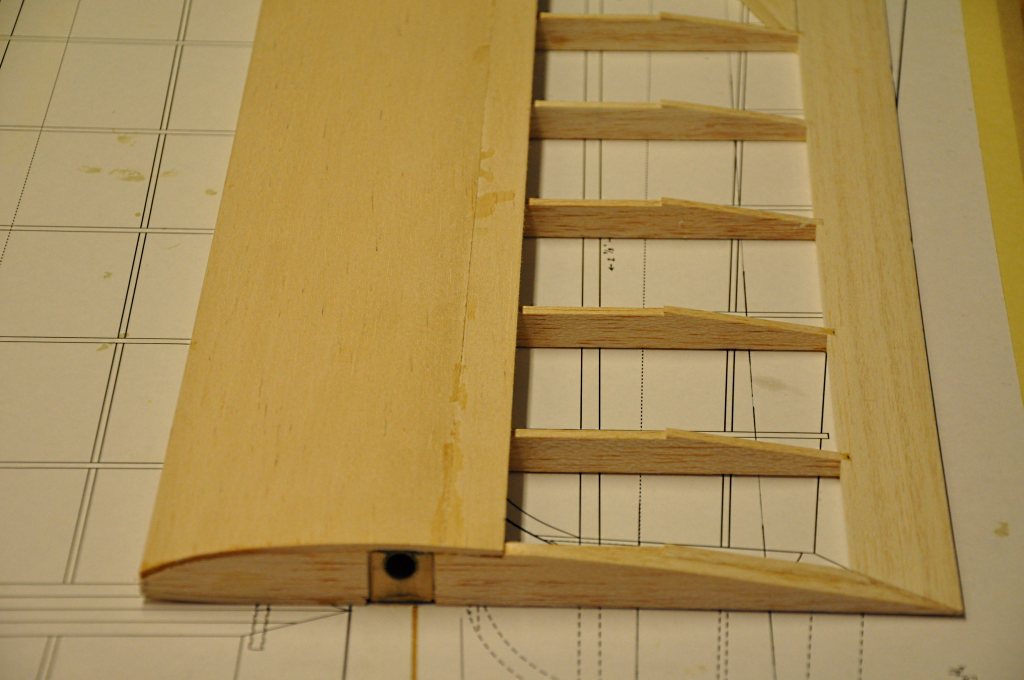
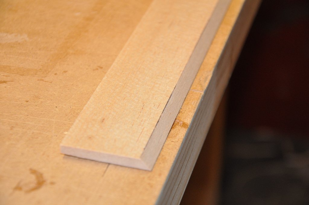
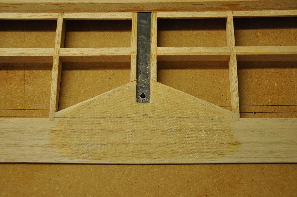
Next the 5 degree angle needed to be sanded into each panel end. I moved the wing end to edge of my bench and blocked up the correct angle for the sanding block. With the block at the proper angle, achieving the right angle was easy and quick.
Unfortunately, I don't seem to have a picture of this process. This picture shows the correct spot, but appears to have been taken before I actually beveled the end ribs.
You may note the spots on the top sheeting: I had to join two sheets to get the proper length and some of the CA got splotchy on me...
Next I installed the components for the spoiler bay.
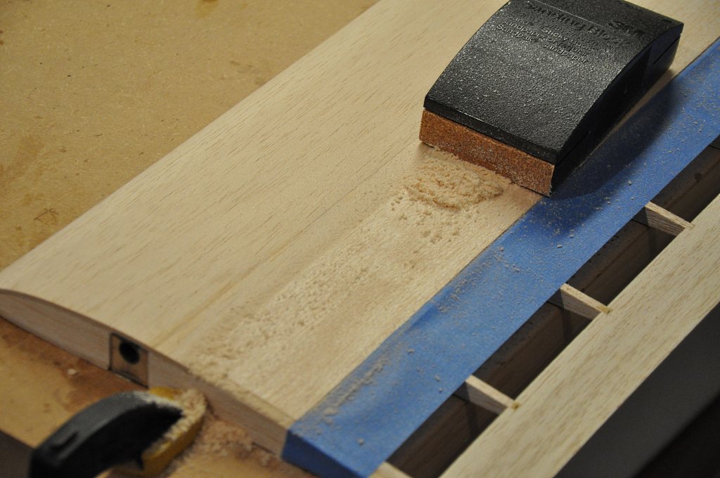
I prepared the bay by carefully running a sanding bar across the bay ribs to ensure everything was flat and even.
I glued in a long triangle piece against the end of the top sheeting. The aft part of the spoiler bay is created by carefully piecing in vertical and horizontal sticks between the ribs.
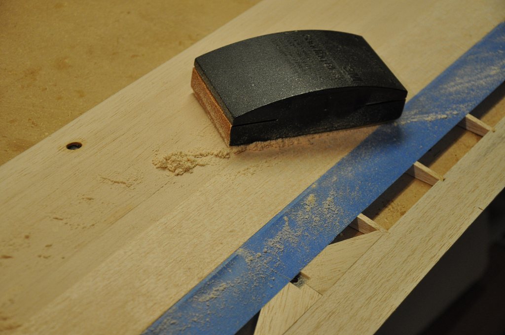
Try for precise alignment of the sticks, but if they're off a bit, you can run a sanding bar over the completed assembly to straighten everything out.
Here is a close-up of the spoiler bay after the various balsa sticks are in place.
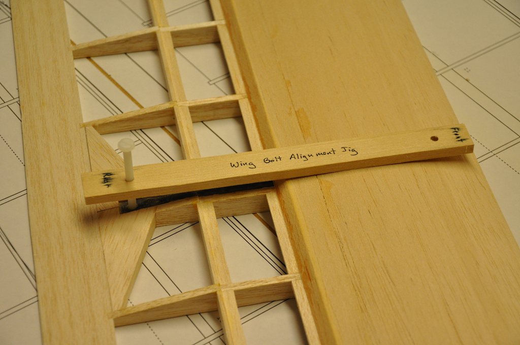
Remember that Wing Bolt Alignment Jig that I made when I drilled the bolt beam holes?
I used it here to find the proper location in the top sheeting where I needed to cut out the bolt head hole. Not a big deal to be sure, but it saved a bit of guesswork.
I moved on to the spoiler itself next.
I inverted my spoiler stock and rough-cut the 45 degree angle bevel that is needed at the leading edge.
I finished the bevel with a long sanding block set at the correct angle.
I set the spoiler into place in the spoiler bay and proceeded to shape the top contour.
The spoiler stock was quite thick, so this step involved removing a lot of material. I used my razor plane to quickly achieve the rough shape.
Once the shape was close, I switched to my block sander and using coarse grit paper I brought the top contour of the spoiler to its final shape.
Finally, I sanded across both spoiler and top sheeting to ensure that the contour was consistent from sheeting to spoiler without any bump or ridge.
Fine grit paper will be used over all wood before covering is done.
And here we see the finished spoiler sitting flush in its bay.
Next, I glued on the outer leading edge strip.
The plans list specific slopes for sanding tangent planes into the leading edge.
To achieve these slopes, I set the wing panel on a .75" oak board. Then I positioned the board at the slope value * .75. (Example: if the slope were 2:1, I set the board back 1.5")
With the sandpaper on only part of the sanding bar I was able to sand the correct tangent into the leading edge.
One of the final steps on the center panel is to glass in the end ribs (see the joiner page for that) and apply glass reinforcement to the center trailing edge.
I made 4 similar patches from 1.5 oz. glass and applied 2 patches to the bottom and top at the same location.
This shot was taken after the glue was cured and the patch was trimmed and sanded.